07.07.2025
International

Recently, advanced ceramic cutting materials with high fracture toughness have been developed for various applications, especially high-speed machining of difficult materials like Ni- or Co-based superalloys. However, their use is limited to turning and milling with solid ceramic tools due to a lack of suitable joining techniques. This challenge can be addressed with a novel joining technique that involves metallizing the ceramic through vacuum brazing, followed by induction brazing with metal in air using flux. In this study, Si3N4 and X37CrMoV5-1 are joined with a stress-reducing Cu interlayer and active filler metal APA5. Joint quality is assessed via wetting test and microstructure analysis using SEM/EDS, while mechanical properties are evaluated through nanoindentation, shear tests, and fractography analysis. The investigations demonstrate that the new joining technique successfully produces metal-steel joints. With a brazing temperature of T = 780 °C, an average shear strength of τ = 155 MPa is achieved. Fractography analysis indicates that fracture primarily occurs in the brazing seam, suggesting a strong bond between the ceramic and the filler metal. This method enables the creation of high-strength ceramic-metal joints, enhancing productivity in the machining of difficult-to-cut materials.
1 Introduction
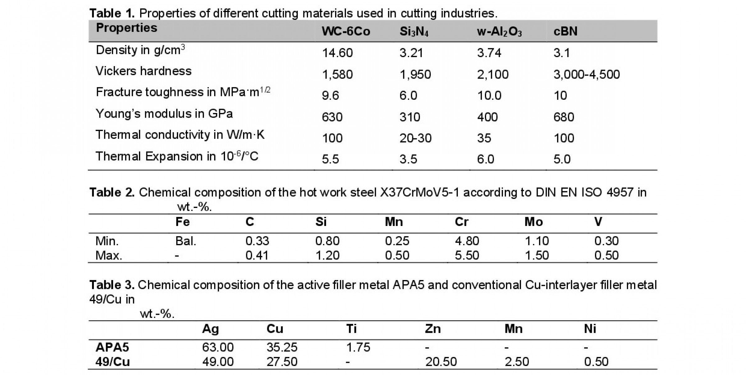
Technological development has increased the demand for using high-strength materials such as Ni-based or Co-based superalloys. In addition to their high strength, these superalloys mostly exhibit excellent corrosion resistance and high-temperature resilience. These high-strength materials are often needed for machines to use them efficiently in different parts. Machining such materials with conventional cutting tool materials such as carbide or high-speed steel results in poor performance and short tool life. According to Deniz et al. [1], silicon nitride-based ceramics provide longer tool life and greater resistance to chipping compared to carbide tools, even when used at higher cutting speeds. Furthermore, they demonstrate lower average surface roughness with less variation during milling. Poorer performance and shorter tool life of carbide is primarily attributed to the alloys’ hard abrasive particles, low thermal conductivity and increased work-hardening rates. As summarized by Devillez et al. [2], these characteristics result in elevated temperatures, increased cutting forces and high shear stresses, accelerating abrasive wear, adhesion and oxidation damage of the cutting edge. On the other hand, high-performance cutting tools made of cubic boron nitride (cBN) or polycrystalline diamond (PCD) show improved performance [3]. However, these tools are often discouraged due to their high price. Ceramic has gained intense concentration as an alternative to these cutting materials due to their high wear resistance and hardness. Typically, alumina-based or silicon nitride-based ceramics are used as cutting tools. Among them, silicon nitride (Si3N4) has caught attention due to its high flexural strength at room temperature and elevated temperatures, excellent creep resistance, low thermal expansion and thermal shock resistance, as concluded by Bocanegra et al. [4]. The properties of different types of cutting materials are shown in Table 1 according to [5] for WC-6Co, [6] for Si3N4 and whisker-Al2O3 and [7] for cBN.
Despite its good properties, the brittleness of Si3N4 hinders its use in various fields. Joining Si3N4 with metal is often required in such cases to harness its superior properties. Various joining technologies have been used for this purpose, including brazing, riveting and adhesive [8]. Because ceramics are prone to cracking or breaking, the mechanical fastening joining technique is not recommended. At present, brazing is the most common technology to join ceramic to metal. The joining mechanism is often known as metallurgical bonding, which allows achieving high-temperature service and high strength of the joint. High joining strength and thermal stability of the joint are crucial for achieving a high cutting rate for difficult-to-cut materials.
In the brazing process, conventional filler metal shows very poor wetting on the ceramic surface due to high interfacial energy resulting from ionic or covalent bonding structure. To improve the wettability on the ceramic, an active element, such as Ti, Zr, Hf, etc., is added to the filler metal, called active filler metal. Ceramic brazing with active filler metal, often called the active brazing process, is a direct joining method. As these active elements possess a high affinity for oxygen, react quickly and form a brittle oxide layer, active brazing is typically conducted in a high-vacuum environment. Another challenge associated with the differences in the coefficient of thermal expansion (CTE). Ceramic has a comparatively lower CTE than steel. The active brazing process typically requires high temperatures, causing a mismatch of CTE during the cooling process. This develops residual stress in the joint and results in lower joining strength. However, residual stress formation can be reduced by using a ductile interlayer between substrates, as shown by Zhao et al. [9], which also contributes to the increase of the joint strength.
Vacuum brazing also has some disadvantages, such as size limitations, high energy consumption and longer brazing time, which often hampers quick production and increases the overall processing costs [10]. On the other hand, induction brazing is a very rapid process. In this process, a high frequency alternating current runs through a coil to induce eddy currents on the component’s surface, which transform into heat. However, ceramics have very low electrical conductivity. Therefore, they must be heated by thermal conduction through the metal substrate. Compared to vacuum brazing, consumption of energy in induction brazing is lower and induction brazing can be carried out in the air. Active brazing of ceramic-metal by induction brazing in air shows challenges in terms of oxidation which yields in no or poor joining.
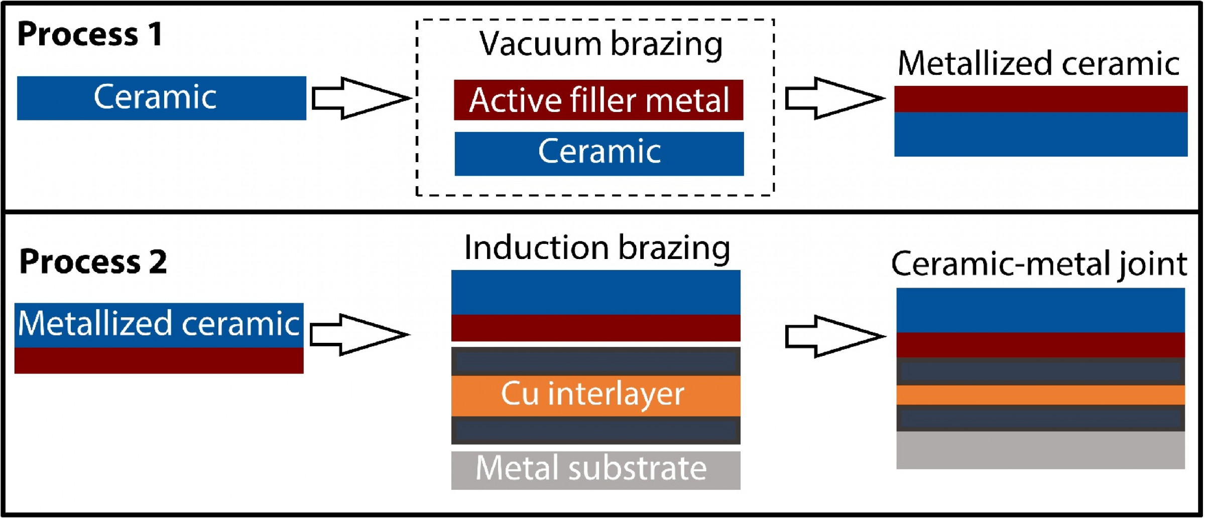
The focus of this study is to efficiently produce a reliable and robust ceramic-metal joint for the cutting tool industry. Successful implementation of the work will help in continuous production compared to batch production. In this study, ceramic-metal will be joined by induction brazing in air using flux. For joining Si3N4 and hot working steel X37CrMoV5-1 will be used. An overview of the joining process is shown in Fig. 1. In the first process, Si3N4 was metallized using an active brazing filler metal through the vacuum brazing process. This step is advantageous from a macro perspective as it allows for the avoidance of geometrical complexity. Additionally, a larger quantity of ceramic can be metallized simultaneously, given that the size of cutting tool tips is typically smaller. In the second process, metallized Si3N4 was inductively brazed in air with the steel using a stress-reducing Cu interlayer. Flux material was also utilized during the brazing process. The flux’s purpose is to aid in the removal of oxides and impurities from the surface of the substrates, enhancing the wetting of the filler metal.
2 Materials and methods
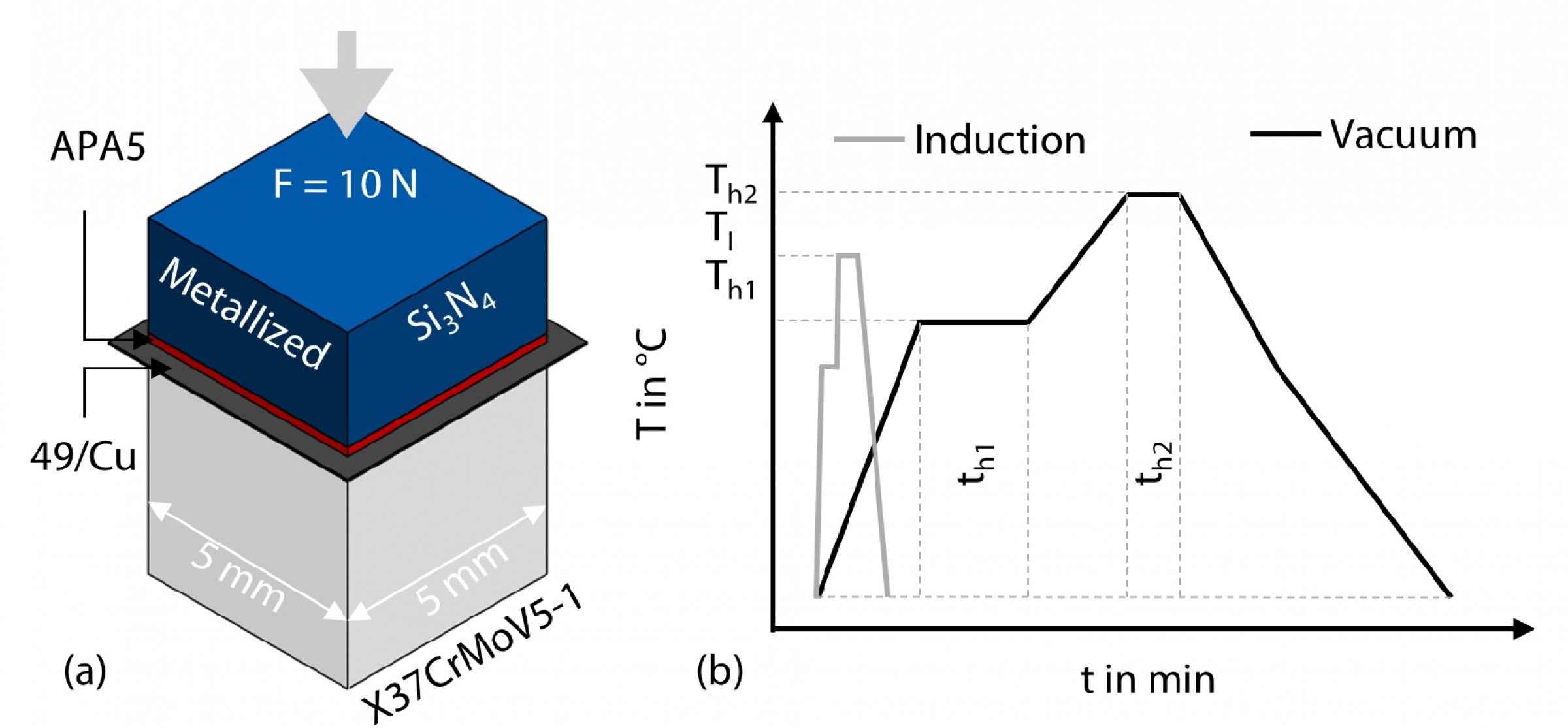
As steel substrate, annealed hot working steel X37CrMoV5-1 was used. The chemical composition of steel substrate is described in Table 2. As ceramic substrate Si3N4 was used. The square shaped steel and ceramic substrate has a cross-sectional area of A = 25 mm². Active filler metal APA5 from Lot-Tek GmbH, Erlangen, Germany, was used for metallization of ceramic by process 1 which has a thickness of dAPA5 = 50 µm. For process 2, conventional Cu interlayer filler metal 49/Cu from Brazetec GmbH, Alzenau, Germany, was used. The thickness of 49/Cu is d49/Cu = 200 µm where the ductile Cu-interlayer has a thickness of dCu = 100 µm. As process 2 is performed in air, fluxing agent type FH 12, FB3-C was used and has a working temperature of 520 °C ≤ T ≤ 1,030 °C. Table 3 describes the chemical composition of the filler metals. Si3N4 ceramic was prepared for metallization by grinding it with 400 grits SiC paper and cleaning it in an ultrasonic bath to remove surface residues. The foil-shaped active filler metal APA5 was then placed on the sample, which was subsequently loaded into the PVA MOV 553 vacuum furnace manufactured by PVA Tepla AG, Wittenberg, Germany. Metallization was performed within the furnace at a heating rate of Ṫ = 10 K·min-1. To achieve homogeneous temperature distribution, the temperature was held at T₁ = 650 °C for th₁ = 30 min. The process then continued with a similar heating rate until the metallization temperature, T₂ = 870 °C, was reached. This temperature is ΔT = 50 °C above the liquidus temperature of APA5. The metallization was held at this temperature for th₂ = 10 min. Throughout the process, a vacuum pressure of p ≤ 10⁻⁵ mbar was maintained.
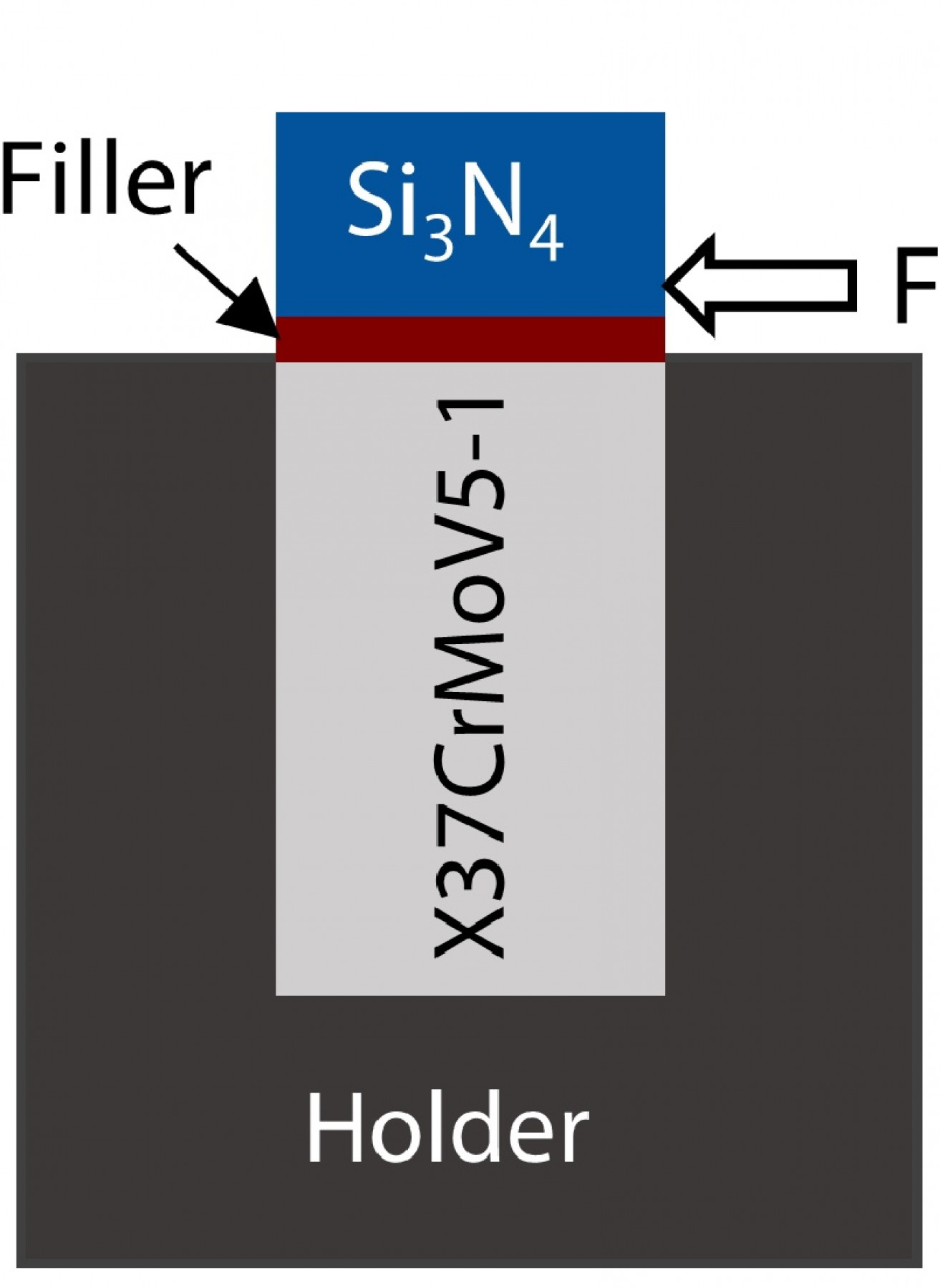
The metallized ceramic was joined with X37CrMoV5-1 using induction brazing. Prior to brazing, the samples were grounded with 400 grits SiC paper and cleaned in an ultrasonic bath. Fluxes were then applied to the surfaces, and filler metal 49/Cu was placed between them. The joints were brazed as butt joints with a force of F = 10 N applied during the process. The induction brazing system was provided by iew Induktive Erwärmungsanlagen GmbH, Gumpoldskirchen, Austria. The samples were heated at a rapid rate of Ṫ = 1,200 K min-1. To achieve homogeneous temperature distribution, the temperature was held at T₁ = 500 °C for th1 = 10 s, which is below the flux working temperature. The samples were then heated again at a similar heating rate. Three different brazing temperatures Ta = 750 °C, Tb= 780 °C and Tc = 810 °C were investigated to examine the influence of the brazing temperature on the subsequent quality of the ceramic-metal joints. The brazing holding time was th2 = 30 s. The temperature was measured using a pyrometer with an emission factor of ε = 0.65. The focus point was set near the brazing joint. It is important to note that there was a variation in temperature readings on the pyrometer, ranging from ΔT = ± 5 - 10 °C, throughout the process. Fig. 2 shows the joining arrangement and processes. The joining quality of the brazed samples is determined by computed tomography (CT) examination. A Zeiss Xradia 520 Versa, Oberkochen, Germany, was used, with a maximum X-ray tube voltage of U = 160 kV. For the measurements, a tube voltage of U = 140 kV and a source power of P = 10 W were applied, with an exposure time of texp = 1.2 s. The distance between the source and the measurement objects was d1 = 38 mm, while the distance between the measurement object and the detector was d2 = 115 mm. At these distances, a voxel size of dv = 17.15 µm was achieved using a 0.4× objective. To obtain high-quality scans, 1601 projections were recorded over an angle of ω = 360°. The metallographic preparation of the samples is carried out followed by cutting, embedding, grinding and polishing. Microstructure analysis is carried out using PhenomX desktop scanning electron microscope (SEM) from Thermo Fisher Scientific Inc, Waltham, MA, USA. The images are recorded using Backscatter Secondary Electron (BSE) mode at an acceleration voltage of U = 15 kV. Contour plots of the hardness are recorded using nanoindentation facilitated by the Fischerscope HM 200XYp from Fischer. The electromechanical shear tester, STM 20-A, sourced from Walter + Bai AG, Löhningen, Switzerland, is used for measuring the shear strength of the brazed samples. Fractography of the samples was measured using light microscope by Axio Imager from Zeiss, Oberkochen, Germany. A schematic illustration of the shear test is shown in Fig. 3. The force was induced into the joint at a speed of v = 0.05 mm/s. In total eight samples from each process were used and an average shear strength was calculated.
The shear strength τ of the brazed joint was calculated using equation (1).
τ = F/A (1)
τ: Shear strength
F: Applied force by the shear tester
A: Cross-section of the sample.
3 Results and discussion
In this section, the results of the conducted experiment are being presented. Various process parameters are being used for ceramic-metal joining via induction brazing. The results of the shear tests show similar results for all brazing temperatures. As a representative example, results at a brazing temperature of T = 780 °C are shown in the following section. This analysis highlights the reliability of the ceramic-metal joint using the induction method.
3.1 μ-CT measurement
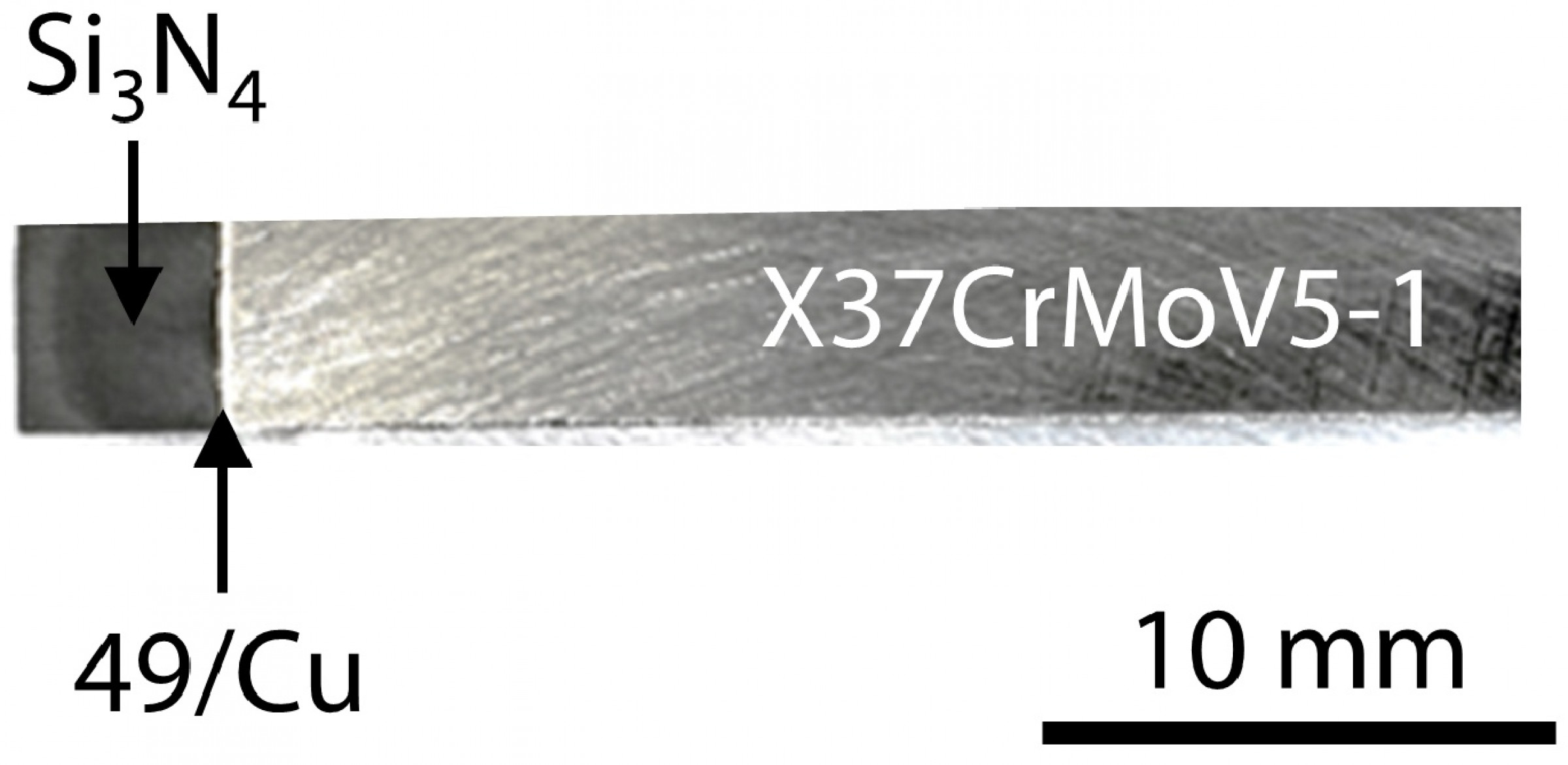
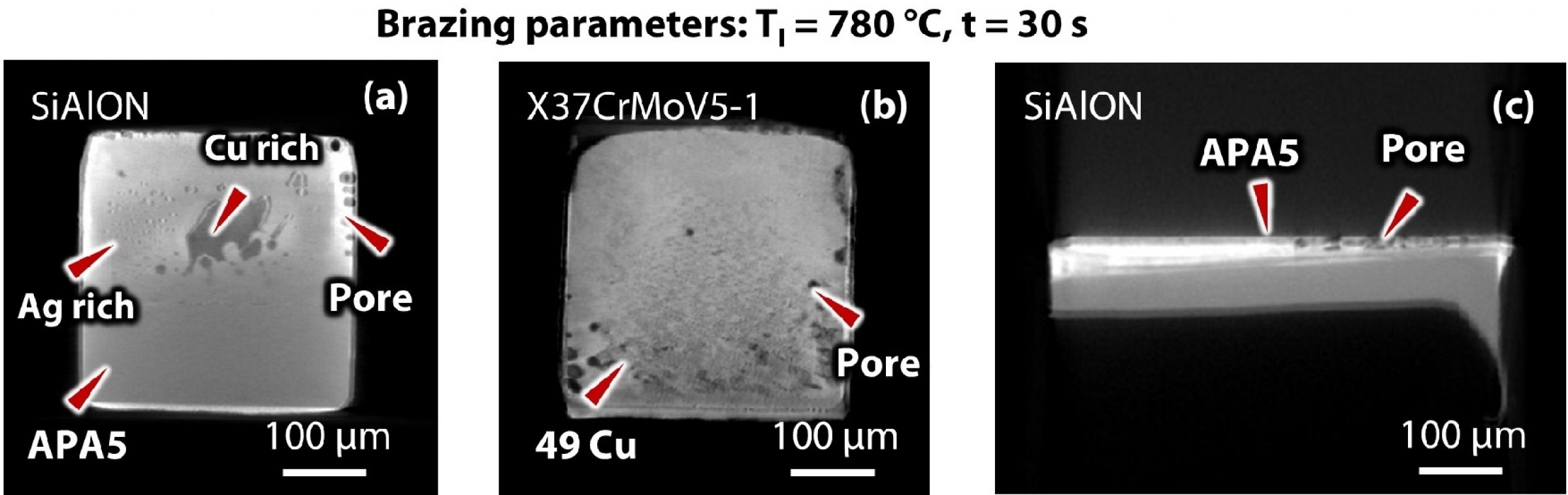
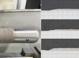
Fig. 4 shows a ceramic-metal joint produced by induction brazing process. Based on visual analysis of the sample, the brazing process appears to create a good joining between the Si3N4 and X37CrMoV5-1. Fig. 5 shows the μ-CT-measurement of the joint. Based on the μ-CT-measurement analysis in Fig. 5, the induction-brazed joints appear to have a good joining quality. The edges exhibit lower wetting. A possible reason could be the evaporation of the Zn content during the induction brazing process. Evaporation of Zn can increase the risk of porosity formation and flowability of the molten filler in the brazing joint. Dimitrijević et al. [11] confirm a significant amount of Zn evaporation above T = 700 °C through a differential scanning calorimetry (DSC) experiment. As the induction brazing temperature exceeds this temperature, evaporation is expected, which also negatively influences the overall joining quality. Additionally, entrapment of flux material during the cooling process might be responsible for low wetting at the edges. The μ-CT measurements show that there is a good wetting on the ceramic side and on the steel side with few, small pores. The pores can vary significantly depending on the sample and have likely contributed to the large standard deviations observed in the shear tests.
3.2 Microstructure analysis
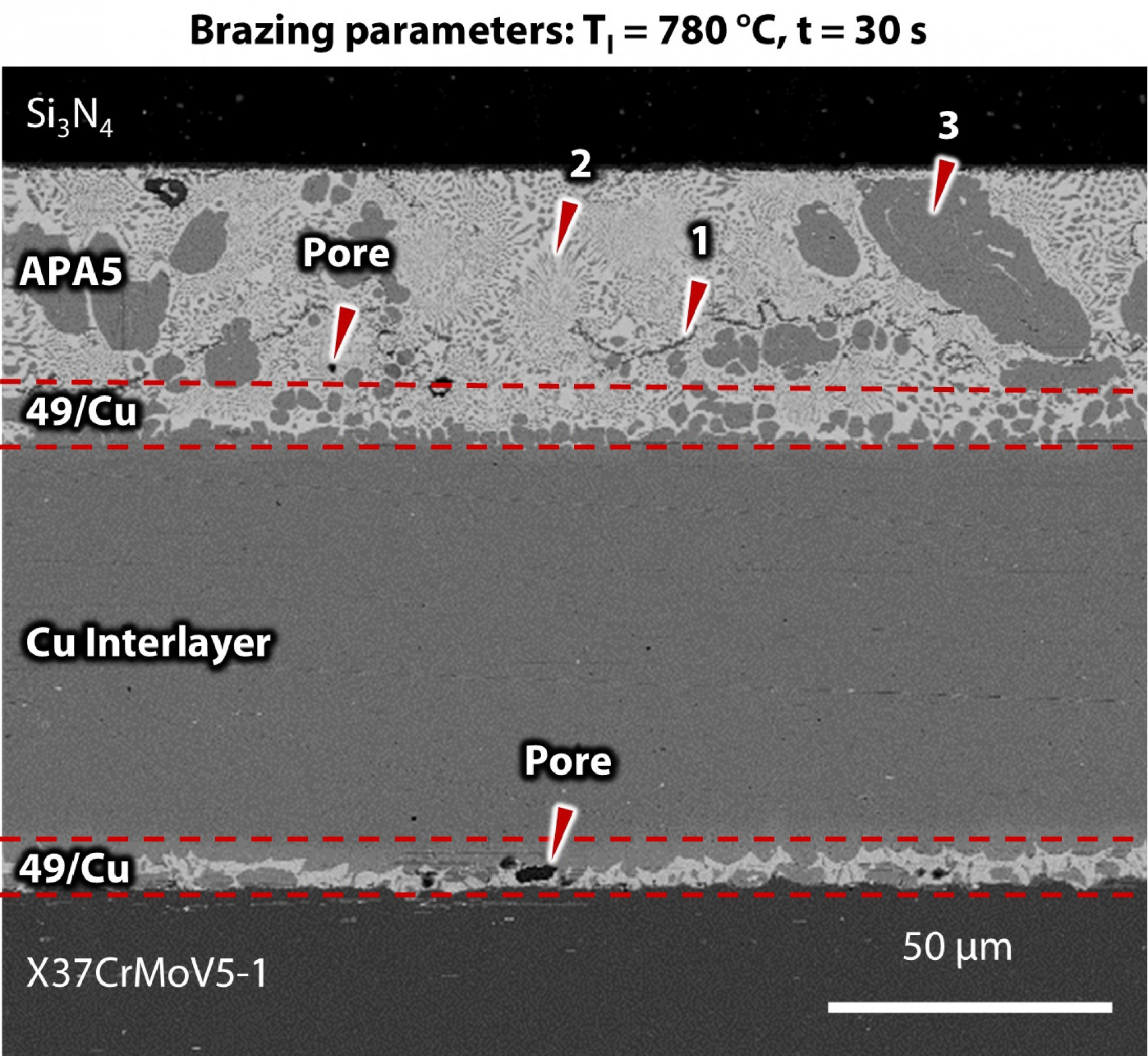
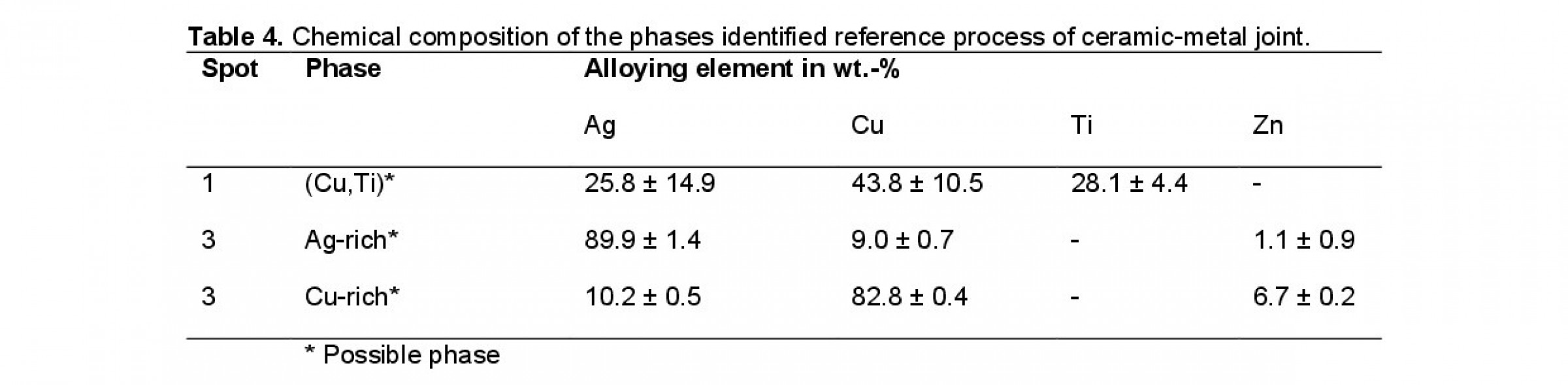
SEM/EDS analysis was performed to evaluate the microstructural characteristics during the induction brazing process. As fractures occur in the brazing seam, microstructural analysis is performed in this area. Fig. 6 shows the microstructural image. The active filler metal APA5 reacted with the conventional filler metal 49/Cu, resulting in a homogeneous mixture. Porosity is observed at the joining interface between X37CrMoV5-1 and 49/Cu, as well as between the active filler metal APA5 and the conventional filler metal 49/Cu. The formation of a solid solution and its distribution throughout the brazing seam are visible in white and grey colors in the SEM image. The white areas are Ag-rich solid solution, while the grey areas are Cu-rich solid solution, as measured by EDS. Additionally, the distribution of a band of black dots, indicated as point 1 in Fig. 6, is also visible. This band of black dots may represent the possible formation of intermetallic compounds (IMC). SEM analysis indicates that the formation of IMCs primarily occurs at the joint between the active filler APA5 and 49/Cu, identified as a band of black dots in the SEM investigation. As the active filler metal contains Ti, the formation of such IMCs is unavoidable in this process. The IMCs have different coefficients of expansion, leading to the formation of residual stress in the joint, which may be responsible for early fracture under load in the ceramic-metal joint. The formation of such IMCs at this temperature is consistent with previous reports [12]. During the metallization process in vacuum, bi-directional diffusion of Ti happens. Although Ti mainly reacts with ceramic substrates, a portion of Ti is still present in the metallized interface. During the induction brazing process, conventional filler 49/Cu melts, diffuses into the metallized parts, reacts with Ti and results in the formation of IMCs. No other types of IMCs are observed after EDS analysis, particularly in the joining area of the filler metal and steel substrate. The EDS analysis is described in Table 4.
3.3 Nanoindentation test
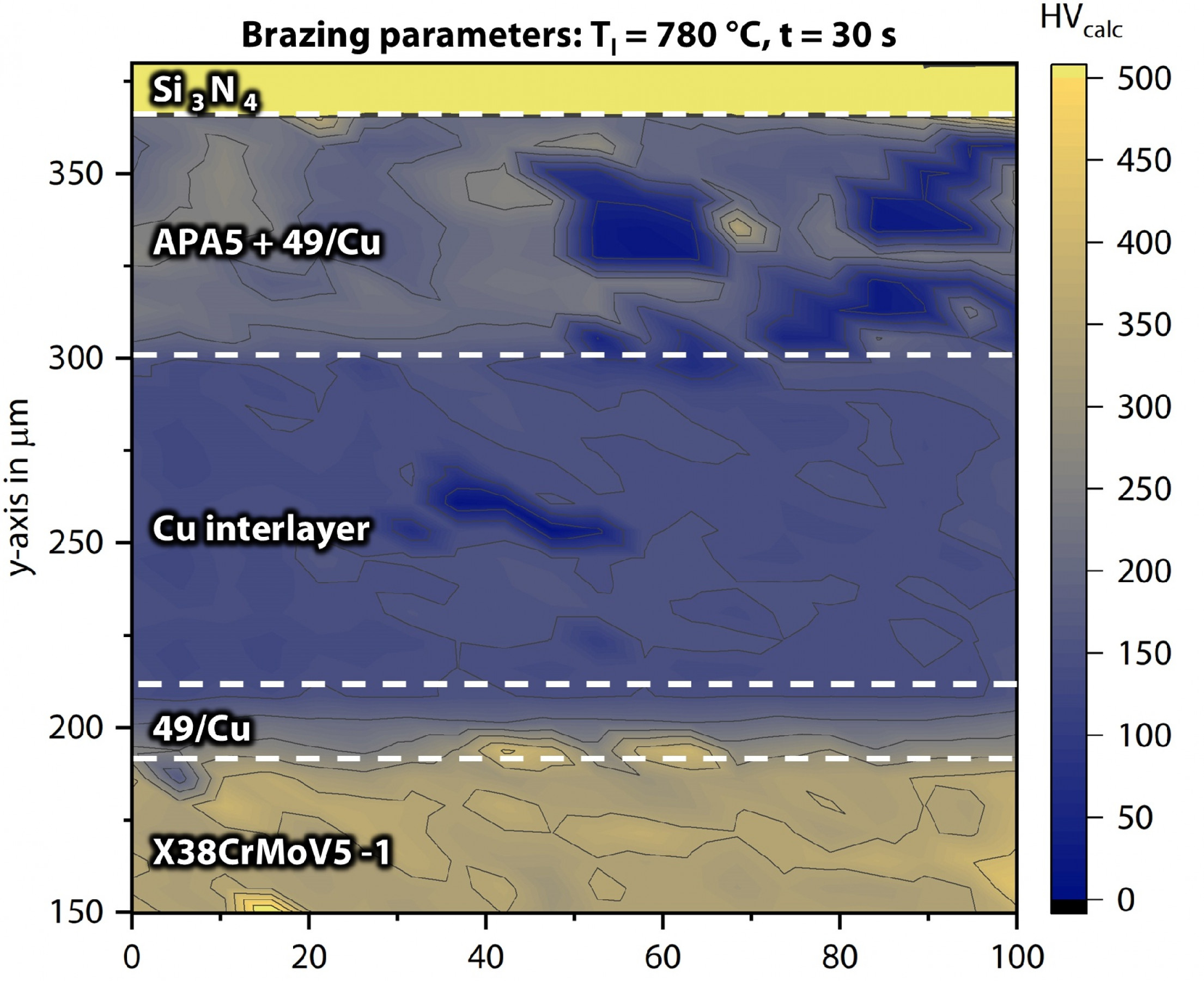
Hardness measurements were carried out to assess the effect of brazing temperature on the brazed joint. The hardness mapping is shown in Fig. 7, where the color bar represents the calculated Vickers hardness (HV) values. The hardness value reached HVcalc ≥ 2,000, corresponding to the ceramic substrate’s hardness. Since fractography indicates that fractures occur in the brazing seam, this study focuses on the range 0 ≤ HVcalc ≤ 500. This range represents the interaction between the active filler APA5, the conventional filler 49/Cu, the Cu interlayer, and the steel substrate. SEM and EDS analyses confirm the formation of IMCs. The hardness measurements reveal significant distribution of different phases, illustrated using a color map. Notably, a much larger inhomogeneity with HVcalc values ranging from 30 to 290 can be observed in the joining area between the 49/Cu and APA5. This variation in HVcalc values can be attributed to the formation of different phases. HVcalc values of 220 or higher may indicate the formation of (Cu,Ti) IMCs, as reported in [13]. Such variations in HVcalc values are responsible for the formation of residual stress, which may contribute to the fracture of the joint. HVcalc values of 90 or lower represent the distribution of Ag and Curich solid solutions.
3.4 Shear strength
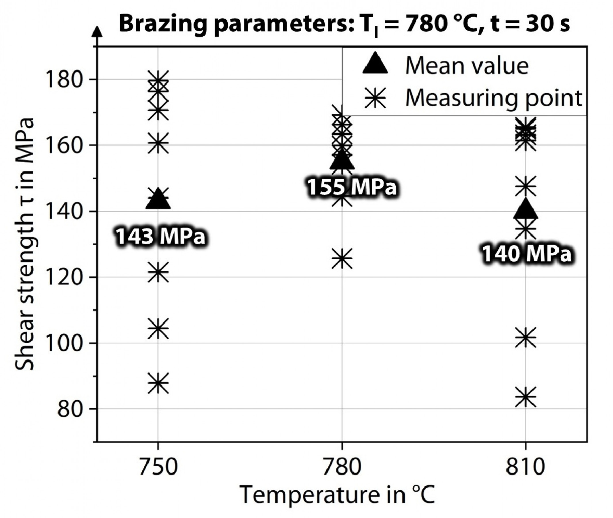
Shear testing is performed following the μ-CT-measurement. The results obtained from the shear test are presented in Fig. 8. The brazing temperature begins at T = 750°C, which is T = 30 °C above the liquidus temperature of the 49/Cu filler metal. Similar shear strengths between 140 MPa < τ < 155 MPa are achieved for all brazing temperatures. The standard deviation, which is 8 % of the average shear strength, represents the similar metallurgical characteristics of the joints. The use of Cu as an interlayer contributes to reducing internal stress development within the joint. However, the formation of defects like porosity can contribute to variations in the measured shear strength. Additionally, the formation of IMCs also influences shear strength by introducing residual stress within the joint. The maximum shear strength recorded for a single sample is τ = 169 MPa. The ceramic-steel joints brazed using the method described herein demonstrate significantly superior performance compared to other active brazed joints. For instance, shear strengths are observed to be below τ ≤ 50 MPa for SiC-steel composites utilizing the same active brazing filler metal as presented here and a TiMo interlayer. In contrast, higher values ranging from 109 MPa ≤ τ ≤ 144 MPa are attained with ZrO2-ceramic steel joints [14]. Optimizing process parameters has the potential to further increase the overall shear strength.
3.5 Fractography
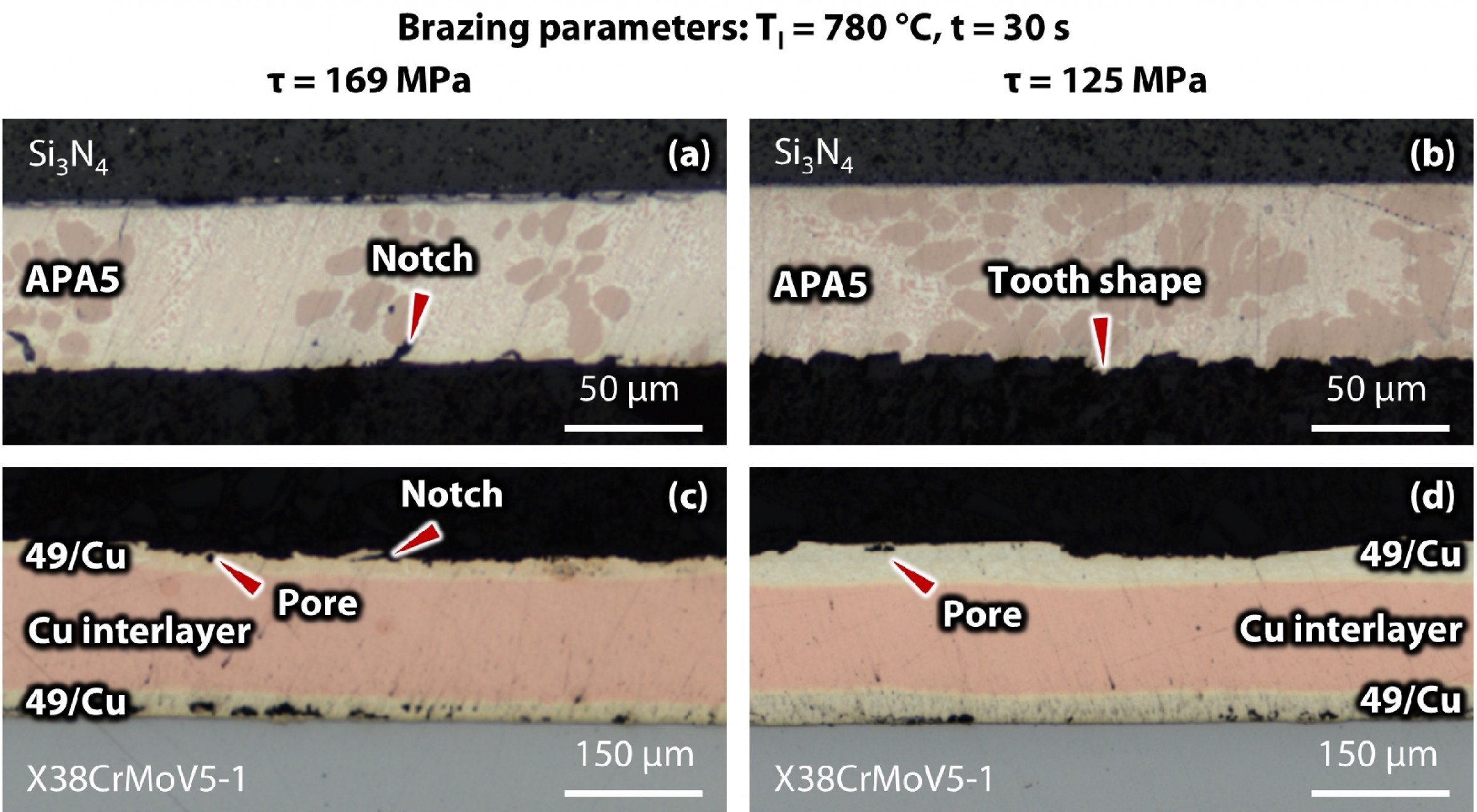
Fracture analysis is performed on samples with the highest shear strength τ = 169 MPa and the lowest shear strength τ = 125 MPa. The fracture path images are shown in Fig. 9. Fig. 9 (a) and (b) indicate that the fracture path primarily occurs within the reaction zone between the active filler metal APA5 and 49/Cu. The observed notch and tooth-shaped fracture morphology is likely associated with the formation of internal stress concentrations in the brazing seam, primarily caused by the formation of different IMCs. These IMCs, with their varying CTE, are responsible for the residual stress formation in the brazing seam. The possible IMCs could be CuTi-based. Detailed microstructural analysis confirms this observation. Since the metallization of the ceramic substrate utilizes a Ti-containing filler material, the formation of such IMCs is unavoidable during the induction brazing process. Fig. 9 (c) and (d) illustrate that fracture occurs in the lower part of the active filler metal APA5. Additionally, the formation of porosity between APA5 and 49/Cu could contribute to fracture formation. This approach effectively avoids brittle fractures in the ceramic substrates in this study. Considering the shear strength and fractography analysis, it can be concluded that the metallization of the ceramic is highly effective, and failure occurs at the interface of the active filler metal APA5, which represents the weak spot of the joint.
4 Conclusion
In this work, efficient joining of metallized ceramic Si3N4 to hot working steel X37CrMoV5-1 is carried out. First, the ceramic is metallized in a vacuum furnace using the active filler APA5. For the joining process, a conventional filler 49/Cu with a Cu interlayer is used. In the second process, the metallized ceramic to the steel substrate is joined using induction brazing. The joining quality is characterized using μ-CT-measurement, SEM/EDS analysis and the mechanical properties are measured via nanoindentation and shear strength tests. The fracture of the joint is investigated using a light microscope to identify the fracture area. The following findings are drawn from the investigation:
▪ The μ-CT-measurement test shows good joining quality after induction brazing. Possible porosity formation is observed at the sample edges, potentially due to flux material entrapment during the cooling process. Additionally, Zn evaporation at high brazing temperatures may negatively influence the joining quality.
▪ SEM reveals a homogeneous mixture of the metallized ceramic part (APA5) and the conventional filler 49/Cu. The formation of IMCs is identified using EDS measurements.
▪ Hardness measurements show an inhomogeneous distribution of hardness values in the joint mixture of APA5 and 49/Cu. This supports the concept of residual stress formation, which may negatively influence the overall joining strength.
▪ The average shear strength achieved is τ = 155 ± 13 MPa at T = 780 °C, with a maximum shear strength of τ = 169 MPa for a single sample. The low standard deviation indicates the reliability of using Cu as an interlayer.
▪ Fractography shows that fracture occurs in the active filler metal APA5, likely due to the formation of IMCs in the joint, indicating that the metallization process was highly effective. In this work, the typical brittle fracture of ceramic shifts towards the brazing seam. Future work can focus on improving the filler metals to enhance overall joining strength. Adapting suitable filler metals can mitigate the formation of IMCs, which may be responsible for lower joining strength. Heat treatment may also reduce the formation of these IMCs. Further analysis can be conducted using Ni as an interlayer.
References
[1] Diniz, A. E., Ferrer, J. A. G.:A Comparison Between Silicon Nitride-Based Ceramic and Coated Carbide Tools in the Face Milling of Irregular Surfaces. Journal of Materials Processing Technology, vol. 206, n° 1-3, p. 294–304, 2008. DOI: 10.1016/j.jmatprotec.2007.12.035.
[2] Devillez, A., et al.: Cutting Forces and Wear in Dry Machining of Inconel 718 With Coated Carbide Tools. In: Wear, vol. 262, n° 7-8, p. 931–942, 2007, DOI: 10.1016/j.wear.2006.10.009.
[3] Klocke, F.: Fertigungsverfahren 1, Zerspanung mit geometrisch bestimmter Schneide. Berlin: Springer, 9th Edition (2018).
[4] Bocanegra-Bernal, M. H.; Matovic, B.: Mechanical Properties of Silicon Nitride-Based Ceramics and Its Use in Structural Applications at High Temperatures. In: Materials Science and Engineering: A, vol. 527, n° 6, p. 1314–1338, 2010, DOI: 10.1016/j.msea.2009.09.064.
[5] Kataria, R.; Kumar, J., Machining of WC-Co Composites - A Review. In: Materials Science Forum, vol. 808, p. 51–64, 2014, DOI: 10.4028/www.scientific.net/MSF.808.51.
[6] Corporation, G., Greenleaf Corporation Technical Ceramics Division, https://greenleafcorporation.com/technical-ceramics.php 11/2/2023.
[7] Arunachalam, R., Mannan, M.A.: Machinability of Nickel-based high Temperature Alloys. Machining Science and Technology 4:127–168, 2000, DOI: 1080/10940340008945703.
[8] Nicholas, M. G., Joining Processes. Introduction To Brazing and Diffusion Bonding. Dordrecht: Kluwer Academic Publishers, 1998, ISBN: 978-0-412-79360-8.
[9] Zhao, Y., et al.: Relief of Residual Stress in al2o3/Nb Joints Brazed With Ag-Cu-Ti/CU/Ag-Cu-Ti Composite Interlayer. Archiv.Civ.Mech.Eng 19:1–10, 2019, DOI: 10.1016/j.acme.2018.08.001
[10] Bobzin, K., et al.: Brazing of Ceramic-To-Ceramic and Ceramic-To-Metal Joints in Air. Front Mech Eng China 5:125–129, 2010, DOI: 10.1007/s11465-010-0007-z.
[11] Dimitrijević, S.P., et al.: Experimental Investigation of Microstructure and Phase Transitions in Ag-Cu-Zn Brazing Alloys. J of Materi Eng and Perform 27:1570–1579, 2018, DOI: 10.1007/s11665-018-3258-1.
[12] Murray, J.L.:The Cu−Ti (Copper-Titanium) system. Bulletin of Alloy Phase Diagrams 4:81–95, 1983, DOI: 10.1007/BF02880329.
[13] Fan, Y., Fan, J., Wang, C.: Formation of Typical Cu–Ti Intermetallic Phases via a Liquid-Solid Reaction Approach. Intermetallics 113:106577, 2019, DOI: 10.1016/j.intermet.2019.106577.
[14] Nascimento, R.M.d, Martinelli, A.E., Buschinelli A.J.A.: Review Article: Recent Advances in Metal-Ceramic Brazing. Cerâmica 49:178–198, 2003, DOI: 10.1590/S0366-69132003000400002
Schlagworte
AlloysBrazingCeramicCeramicsInductionJoiningMaterialMaterialsMetalResearchStudyTechnology
![SCHWEISSEN & SCHNEIDEN 2025 [EN]](/images/frontend/journals/dvs-sus_sm.png)