03.11.2026
Wissenswertes
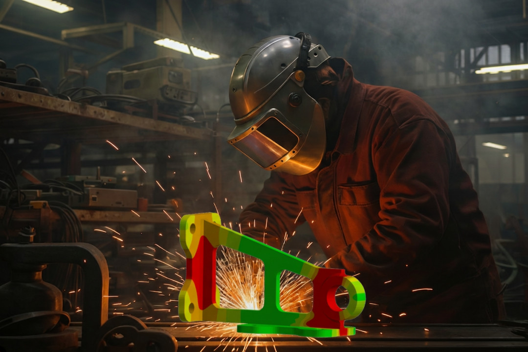
How does one get a perfect welding process right from the start? Welding process simulation helps master these complex manufacturing operations. Ansys now supports the setup of the joining process: weld direction and sequence can be easily varied. This clears the way for calculating temperature field, weld distortion and residual stresses.
Welding processes are complex and characterised by a large amount of heat being introduced locally into a component. This material is melted and the fusion of the material joins the components. Welded assemblies typically consist of a large number of seams. Distortion is unavoidable. There is a wide variety of welding methods with many different process parameters. These have to be adapted depending on the application and component. To get this complexity under control, engineers can use simulations in order to set up the process properly.
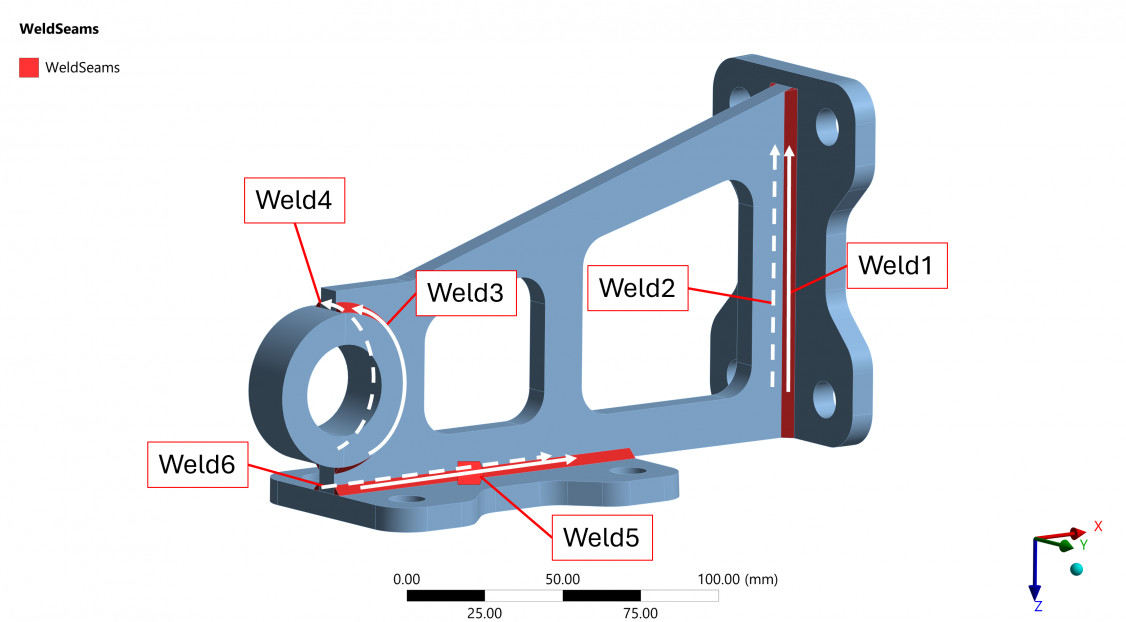
But the simulation is not simple either. First of all, this involves transient processes. Users have to consider both thermal and structural mechanical effects. To capture the process, a moving heat source is needed. Material is heated, melts and then solidifies again. The weld seam forms step by step. To calculate the distortion, the time-varying temperature field must first be determined. However, if the welding sequence changes, the heat source suddenly also changes, and thus the model must be adapted, too. Usually, this requires considerable effort. An example: Take a welded assembly made up of several sheet metal parts joined by fillet welds. The assembly is joined in several locations and in different welding directions. Three-dimensional effects also play a role here: alongside seams in the X and Z directions, one seam runs tangentially along a round part that is welded into a round recess.
Simpler creation of welding models
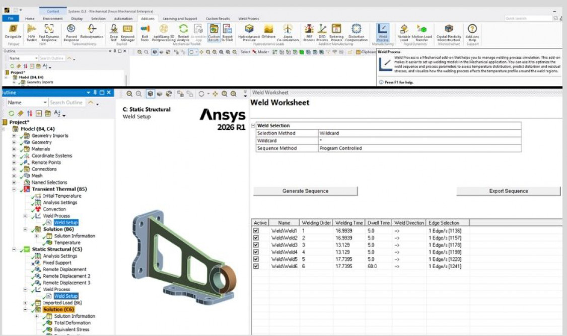
In order to depict the welding process, simplifications have to be made. Until now, these have been performed in Ansys using custom-written routines. The “Weld Process” add-on, a new native extension of the Ansys Mechanical software package, combines most of the necessary functionality and simplifies the creation of welding models directly within Ansys Mechanical. Whereas in the past it could take hours to set up a suitable model, this is now possible much faster with good preparation. The basic goal is to determine the temperature distribution during the process and to predict distortion and residual stresses.
There are three calculation variants:
- If the user is only interested in the temperature distribution, a transient thermal analysis is sufficient. It is significantly less demanding and therefore a good first analysis.
- There is also the option of running only a structural mechanical analysis. Since information on the temperature distribution is then missing, the thermal strains have to be calibrated using measurement data and scaled accordingly via the „Thermal Strain Scaling Factor."
- The classic case is a transient thermal analysis followed by a sequentially coupled mechanical analysis
The weld seams are integrated as solid bodies, ideally named and numbered unambiguously.
The order and direction of the seams can be defined as can the pause times between individual seams. In addition, process parameters such as melting temperature, ambient temperature and welding speed can be entered. These parameters ulitmately determine the level of the component's distortion. The elements in the weld seam are „clustered," meaning groups of elements are created. These clusters are activated one after another and supplied with heat, so that the weld seams build up step by step and a moving heat source is created. The user determines the size of the clusters. Optionally, a Goldak heat source can also be used.
Coupled thermal and mechanical simulation
Since temperatures go up to the melting point, the process simulation requires temperature-dependent material data. In addition, a plastic material model with likewise temperature-dependent stress-strain curves is required. Corresponding data can be found, for example, in the Engineering Data Sources under Additive Manufacturing Materials. In this case of coupled simulation, the two analyses are solved sequentially: first the temperature field, then the structural mechanics. The number of load steps results from the number of element clusters and any cooling steps.
Depending on the welding process, it can be chosen between two variants: for material deposition, element kill/alive technology is used to create the weld elements, e.g. in a fillet weld. To simulate the welding process without filler material, direct energy deposition simply applies heat, with no activation or deactivation of elements. The heat input itself can be defined via the applied temperature or the applied power. In the background, the reference temperature for the weld seam solid bodies is automatically set to the melting temperature.
Since the entire process is modelled, corresponding computation times have to be considered. As so often, the challenge is to find the middle ground between a fast and a meaningful simulation. For a first attempt (at least for the weld distortion), a fairly coarse weld seam mesh with only a few elements in the weld seam cross-section can already give a good impression of the structure's behavior. Once the model is set up, one can very easily make changes to the weld sequence, the weld direction or the process parameters.
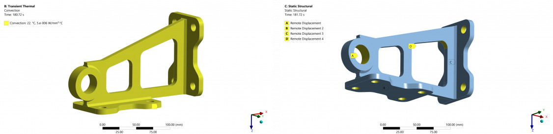
The heat source over time
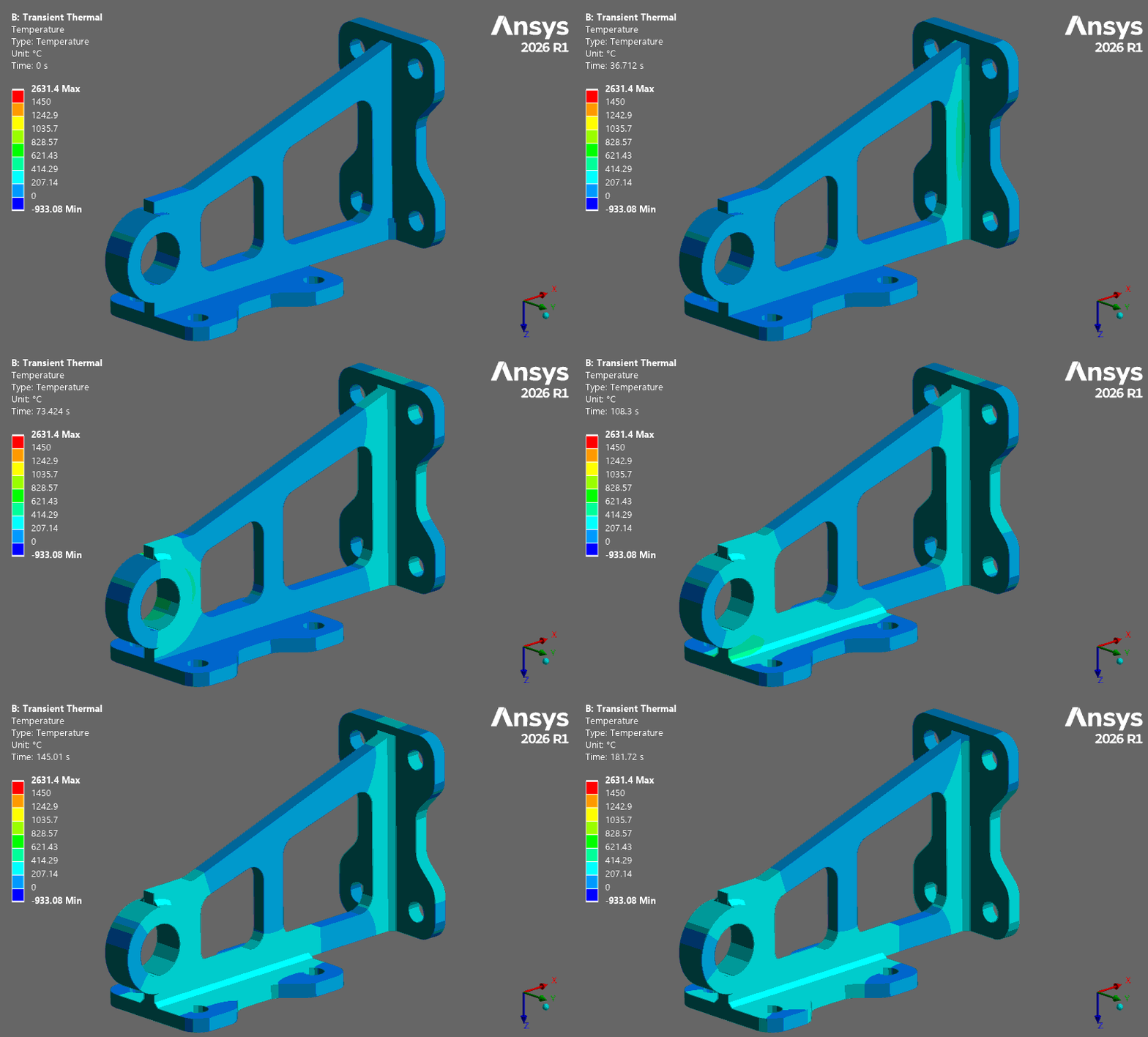
Probably the most exciting result of the transient thermal analysis is the changing temperature field during the process. Depending on how far the heat source has already progressed along the seam, every point in the component reaches its maximum temperature at a different time. A „special" result available only for the thermal part of the welding process simulation is the so-called weld penetration result: It shows where and how strongly the heat penetrates the component, helping to identify critical areas (heat-affected zones). It is precisely there that the material's microstructure often changes due to the high thermal load, which can affect the later strength.
By watching the temperature result animated, one can observe the moving heat source. At the start of the process, as no weld seams are present yet, the seams form step by step, or „cluster by cluster," as described earlier. This makes it possible to directly follow how element activation works in practice and how the heat actually spreads through the component in the process. This exact time-dependent development provides the basis for everything that is subsequently calculated in terms of distortion and residual stresses. Once the mechanical analysis is complete, one can also display the temperature result as a User Defined Result (expression: BFE). This allows the user to additionally visualise the deformation behaviour. It is best to increase the displacement scale factor for this. At the same time, the temperature is shown as a contour plot. In the region of the heat source, the thermal strains are clearly visible.
Deep insights into distortions
If one reverses the sequence or direction of the weld seams – which is easy to change – the weld distortion changes significantly. For the variant with a changed welding direction, the distortion increases by almost 37% compared to the initial variant; for the variant with reversed welding sequence, by 39%. In this case, the structure deforms in the opposite direction (positive y-direction), while the other two variants deform in the negative y-direction. The initial sequence turns out to be the one with the least distortion. With a sufficiently fine mesh, the residual welding stresses that develop after cooling to room temperature can also be evaluated.
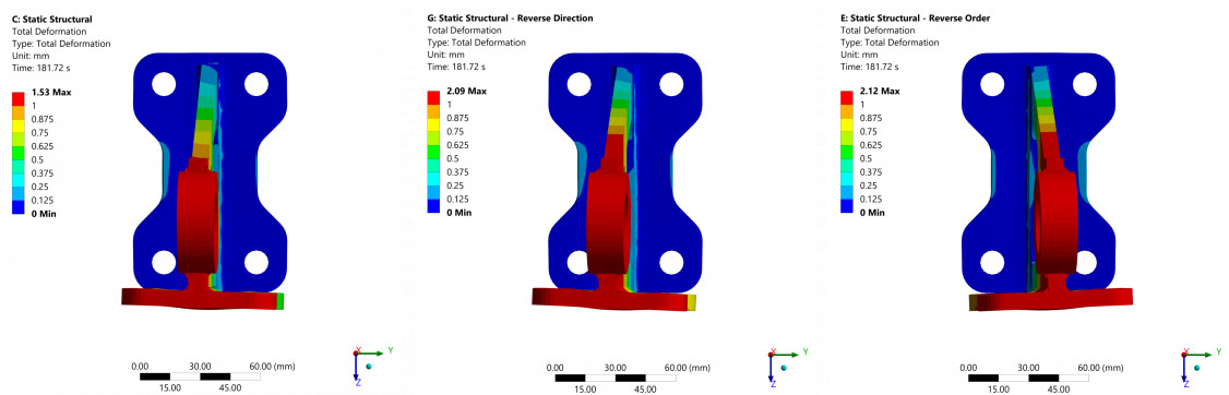
Who really knows which sequence or welding direction is best? And who wants to try them all out? For smaller assemblies like this one, an estimation of distortion tendencies may still be feasible; however, for larger structures, this approach becomes considerably more challenging. It requires a lot of experience. How many possible combinations are there? The example shows how a welding process can be set up and the process simulation be carried out. The user is supported by the new Weld Process add-on of the Ansys software. This makes it much easier to create variations in the welding sequence and direction as well as in the process parameters.
(Author: Sebastian Hoffmann, Application Engineer, Cadfem Germany GmbH)
Schlagworte
Additive ManufacturingDEDDirected Energy DepositionDistortionJoiningResidual StressSoftwareWeld DistortionWeldingWelding ParametersWelding Simulation